Money can be saved and the safety improved on Norcold N400, N401, N500, N501, 442, 443, 452, 453, 462, 463, 482, and 483 by installing the ARP failure prevention device. This page is an installation overview.
REQUIRED TO DOWNLOAD INSTALLATION INSTRUCTIONS - WEB PAGES ARE SUPPLEMENTAL - EACH VERSION OF CONTROL HAS INTRICACIES REQUIRING THE WRITTEN INSTRUCTIONS.
Some of the Norcold 400 and 500 series are manually controlled refrigerators, such as the N400 & N500. An example of a manually controlled refrigerator requires the operator to hold down a gas valve button to ignite the gas flame. The ignition process is either turned on with a switch, or the igniter is operated by pushing a button.
The operator has to hold down the gas button until the gas flame heats a thermocouple. The thermocouple will keep the gas valve open and only then will the operator release the gas valve button. If the flame goes out, the thermocouple will automatically close the gas valve, this is the safety device that prevents unburned gas from accumulating and resulting in a fire hazard.
The above described 'manual control' is a very dependable time tested method for controlling the gas flame. The down side for the ARPrv Control is that the ARP can only turn off the gas flame if the boiler overheats. The ARP cannot restart the gas flame after the flame has been extinguished because the operator needs to manually hold down the gas valve button. Although this is an inconvenience when compared to the 'automatic control', one would much rather turn off their fridge than destroy it!

This diagram is a wiring overview for the manual control type refrigerator.
Although this diagram is for the v2.x ARP Control, the wiring is similar for the
older ARP v1.x controls which are described below.
Click here for required Tyco P/N 1432793 Relay
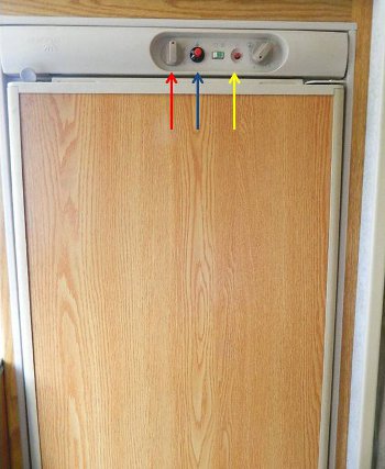
The photo to the left is a Norcold N400 installed in a 2002 VW Winnebago Vista. This RV has been in full time use for 2 years. The entire RV, including the refrigerator is very well maintained.
The red arrow points to the heat selector switch. For the ARPrv Control, the only heat source we are going to provide protection for is the LP gas. We assume that folks will be leveled when they use shore power.
The blue arrow points to the igniter button.
The yellow arrow points to the gas valve button.
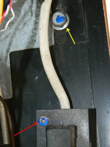
In a Winnebago the fridge is removed by taking out 4 screws that are inside the refrigerator door, these screws hold the door frame to the wood around the fridge.
Remove the gas line at the rear of the fridge only after turning off the LP gas. Be sure to bubble test the LP gas for leaks upon reinstallation.
The yellow arrow points to one of the 4 bolts that hold the fridge frame to the vehicle; this photo is looking in through the outer cooling unit access door.
The red arrow points to the 120VAC plug, the two screws needed to be removed from the power plug.
Finally, the 12VDC power and ground need to be removed from the back of the fridge.
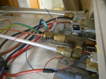
This photo shows the top of the Norcold with the dust cover removed.
The yellow arrow points to the gas valve button assembly.
The red arrow points to the thermocouple that goes to the burner. When the thermocouple is hot it should product around 6 - 10mV.
The blue arrow points to the red wire that will be spliced so that the ARPrv Relay can be put in line with this wire.
Before removal, the 12VDC power and ground need to be removed from the back of the fridge.
Be careful, all fridges are installed a little differently depending on the RV.
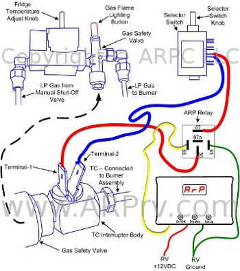
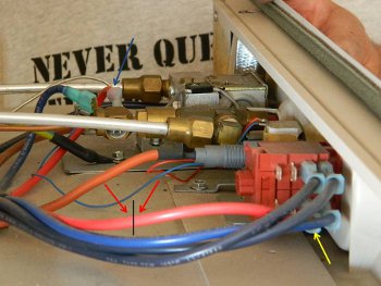
The wiring diagram and the photo to the left show the red wire going from selector switch terminal 2a (yellow arrow) to the thermocouple interrupter (blue arrow).
This red wire will be spliced at the red arrows. Two female spade connectors will be used to connect the ARPrv Relay at terminals 30 and 87, the normally open terminals of the relay as seen in the figure to the far left.
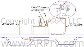
The drawing to the left shows the gas valve control assembly for the 442, 443, and 462 Norcold fridges. For these fridges the Norcold part number 621737 is required for interrupting the thermocouple signal to the gas valve.
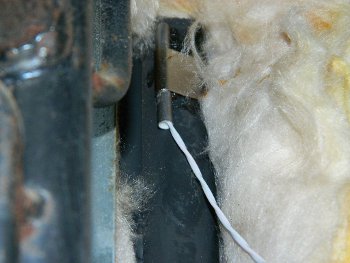
This photo shows the temperature sensor installed on the boiler tube.
The Norcold 4xx series of fridges are very dependable refrigerators, this series include the N400, N500, 442, 452, and 462.
The Fridge Defend by ARP could help your refrigerator last the lifetime of your RV!