This video shows the Norcold temperature sensor install for the Fridge Defend by ARP.
NOTE: There is no need to get the sensor as high on the boiler as possible. This video was made when RV manufactures installed the refrigerators so one could access the boiler up to 4 inches above the heaters. We now recommend installing the boiler sensor just above the electric heater element. Be sure to insulate the sensor so that it reads temperature from just the boiler tube, not electric heaters or flue tube.
We produced this animation to show how easy it is to install the Fridge Defend by ARP temperature sensor. This video shows a typical Norcold temperature sensor install, please see the ARP install instructions because this page in only a visual to aid the installer.
Click here to see video of why Norcold fridge fails.
Please note that this video does not apply to the N3104, N3150, N4104, N4141, N4150, N4151 or the Polar 7, 8,
& 10 series, the boiler tube is behind the flue tube on these models.
Click here for the N3104 & N3150 installation.
Click here for the N4104, N4141, N4150 & N4151 installation.
Click here for the Polar 7, 8, & 10 installation.

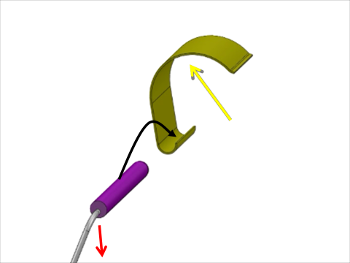
The first figure shows the general process to align the ARP temperature probe and clip to install on a Norcold boiler. By placing a small amount of super glue in the clip at the end of the black arrow, the ARP temperature probe can be attached to the clip for easy one handed installation. Please note the red arrow, if the wire is offset in the temperature probe, position it so that the offset is to the outside of the clip. This makes it easy to insulate between the wire and boiler tube in the last step. Also, the yellow arrow points to the inside of the clip where some silicone grease can be placed to make the probe assembly easier to move once on the boiler tube.

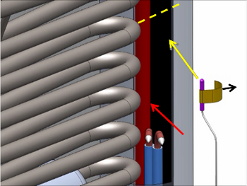
This next capture from the above video shows the temperature sensor install alignment on the boiler tube. In this image the boiler tube is black, the red arrow points at the flue tube which is red. The easy way to detect the boiler tube is by the fact that the electric heater mounts are welded to the boiler tube. Please note that the black arrow show the direction the clip is attached, this makes it easy to slide the sensor away from the flue tube once attached. Also in this figure, the yellow dashed line shows the next to top absorber coil. The sensor should be no higher than this coil and not any lower than one inch above the electric heater elements.

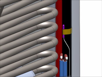
This next image shows the sensor snapped onto the boiler tube, but the sensor is too close to the flue tube. Be sure to rotate the sensor away from the flue tube, then pack insulation between the sensor and flue tube if necessary to prevent an air gap.

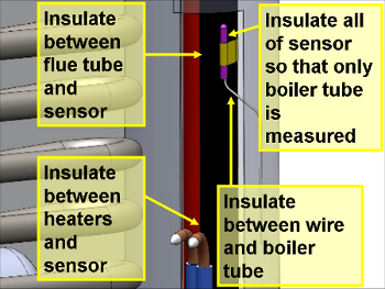
Please insulate the sensor well. Fiberglass insulation is easy to obtain, pack it between the sensor wire and the boiler tube. Also pack between the electric heaters and the flue tube and the sensor. Finally, cover the sensor with insulation and fill the boiler housing with insulation to make your fridge more efficient.