A well built Norcold N145 or N150 will last the life of your RV when it is protected by the Fridge Defend, this pages shows how to install boiler overheat protection on your fridge.
REQUIRED TO DOWNLOAD INSTALLATION INSTRUCTIONS - WEB PAGES ARE SUPPLEMENTAL - EACH VERSION OF CONTROL HAS INTRICACIES REQUIRING THE WRITTEN INSTRUCTIONS.

The Norcold N145 and N150 refrigerators are manual control type of refrigerator. This means that one has to hold a button down and ignite the gas flame.
The first figure on this page shows the N145 & N150 control panel, the yellow button is pushed to ignite the LP gas flame. It is on the backside of this button that the Fridge Defend is wired into the system.
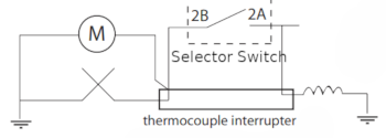
This is the N145 of N150 wiring diagram, where:
•
Selector Switch terminals 2B & 2A are wired to the Thermocouple
Interrupter.
•
This diagram is a block diagram where 'M' is the volt meter.
•
The coil on the right is the gas valve.
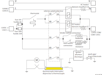
Yellow is the thermocouple interrupter seen in the above image.
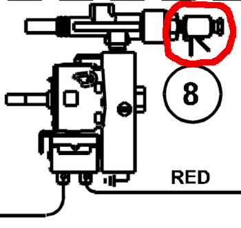
This is a close up of the above interrupt adaptor circled in red as it would appear on the backside of the selector switch that is pushed to turn on the LP gas.
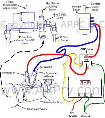
Referencing the Norcold N145 & N150 Mode Selector Switch image above, the thermocouple interrupt adaptor is wired to the Norcold this switch. Terminals identified as '2A' & '2B' above in the wiring diagram, the wires colors are identified in the manuals as red and black. We are told that the wires can be orange or red and blue, the installer needs to identify the proper wires .
The ARP relay will be spliced into one of the sets of wires coming from the interrupt adaptor to the selector switch. Two female spade connectors will be used to connect the Fridge Defend Relay at terminals 30 and 87, the normally open terminals of the relay as seen in the figure.
The relay should be mounted as close to the control as possible. That is, the wires to the relay need to be as short as possible.
Please click here for another view for wiring the interrupt adapter.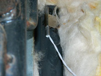
This photo shows the temperature sensor installed on the boiler tube.
The Norcold N145 series of fridges are very dependable refrigerators as long as the boiler is not allowed to overheat.
The Fridge Defend by ARP could help your refrigerator last the lifetime of your RV!
If you cannot find what you need please use the Contact Us form on the top menu.