To save money and improve safety on Norcold Cooling Unit 1200, 1201, 1210, 1211 the Fridge Defend by ARP failure prevention device should be installed. This page is an overview of how to install the boiler temperature sensor.
REQUIRED TO DOWNLOAD INSTALLATION INSTRUCTIONS - WEB PAGES ARE SUPPLEMENTAL - EACH VERSION OF CONTROL HAS INTRICACIES REQUIRING THE WRITTEN INSTRUCTIONS.
Instructions: Subjects are listed on left. Click the link to the right to go directly to the subject matter on this page.
The following information describes how to install the Fridge Defend boiler sensor. This insulation will improve the performance of your refrigeration system. Our experience has shown that often the cooling unit boiler assemblies of these units are poorly insulated due to the NHTSA recall kit at the location where the sensor is placed. See the first photo below, this cooling unit was replaced and the installer did not replace the insulation properly.
Often the boiler insulation is installed in such a manner that it allows heat loss from the boiler area. This will result in poor performance for the fridge. Following we will show the Fridge Defend temperature sensor installed on the two types of Norcold 1200 series cooling unit boiler housing assemblies. The new style of boiler housing (Year 2013 on) will be demonstrated first.
After purchase, more detailed instructions on the installation of the Fridge Defend temperature sensor may be downloaded. Please also reference the NHTSA Norcold Recall Installation Document. Further information may be obtained directly from the NHTSA.
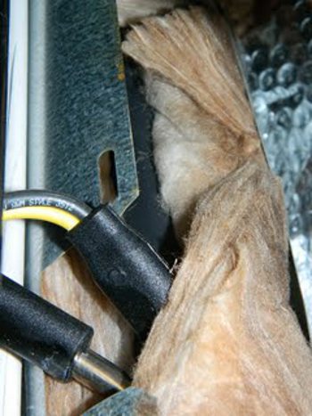
This photo shows the newer design for the Norcold Cooling Unit 1200, 1201, 1210, and 1211 series boiler assembly. Note that the boiler is now encased in a sheet metal boiler housing that contains the insulation. This photo is with the heater access door removed so that the Fridge Defend temperature sensor can be installed. This boiler housing is on all new 1210 OEM Norcold cooling units, these cooling units fit the 1200, 1201, 1210, and 1211 fridge.
Please note the insulation in this photo, this is just how it looked before the Fridge Defend temperature sensor was installed. This Norcold 1201 had the new style cooling unit installed and the insulation was never covering the boiler tube. This fridge cooling unit ran all the time due to the lack of insulation. During the following temperature sensor installation we will show how to help your cooling unit perform at its maximum capability.
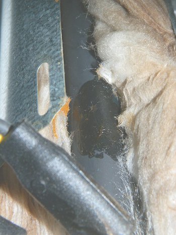
This step is optional, but recommended, it helps with sensor alignment. Silicone grease is used in this example, silicone spray can also be use.
Silicone grease is applied to the boiler tube at the location where the temperature sensor is to be installed. The grease should also be applied to the temperature sensor clip before installation. This will help with moving the temperature sensor on the cooling unit once the Fridge Defend by ARP sensor is snapped onto the boiler tube.
Please see the complete installation instructions for more information on where to get silicone grease.
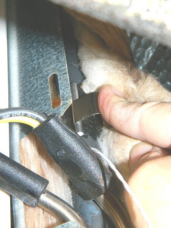
As per the detailed instructions, once the temperature sensor has been secured to the clip, the Fridge Defend temperature sensor is snapped onto the Norcold cooling unit boiler tube.
It is important at this point to insulate the boiler sensor very well. Put insulation between the sensor wire and the boiler tube, then insulate the top of the sensor and between the boiler tube and the boiler housing. One should not be able to see the boiler tube, if the boiler tube can be seen, there is not enough insulation in the boiler housing. Please see further instructions below.
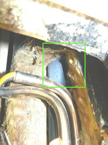
We will continue by showing the old style foil wrapped cooling unit boiler housing. Please use the instructions above, the only difference between the early and late style is the boiler housing, the sensor installation on the boiler tube is the same.
This type cooling unit is original equipment on the 1200, 1201, and 1210 model. It is optional to remove the Norcold Recall Kit insulation. This photo shows the kit insulation removed to aid the viewer. The green box shows the section of insulation that needs to be removed in order to install the ARP temperature sensor on the cooling unit boiler tube.
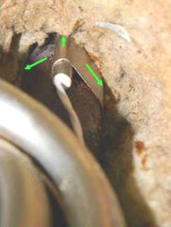
This photo shows the final location of the temperature sensor. The green arrows show where to put additional insulation.
It is very important to align the temperature sensor so that it cannot be heated by either the flue tube or the electrical heating elements on the cooling unit. The temperature sensor should be 1 inch above the electric heaters as seen in this photo. If necessary, rotate the temperature sensor & clip around to the right - away from the cooling unit flue tube and insulate any air spaces.
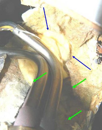
This photo shows the Norcold 1200 insulation between the cooling unit boiler tube and the Fridge Defend temperature sensor wiring.
Insulate the temperature sensor by packing insulation around all sides of the sensor, and between the sensor wiring and the boiler tube (blue arrows).
Please be sure to pack plenty of insulation around your electric heaters (green arrows).
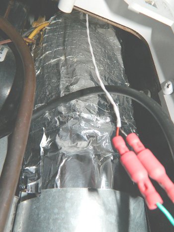
This photo shows the boiler housing after the Norcold Recall insulation has been reinstalled on an early 1210 model (c2006). The Fridge Defend temperature sensor wiring exits the insulation at the top, away from the electrical heating wires. Use HVAC aluminum tape to re-attach the insulation on the older foil type boiler housing.
Be sure to push the foil cover on the Norcold insulation around the back side of the boiler housing so that no gaps are present. Tape all edges that are accessible to create a tight seal.
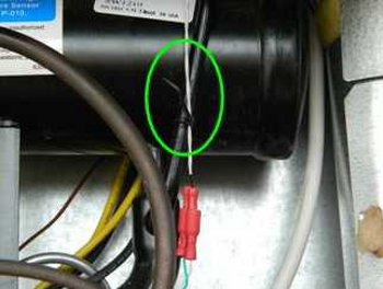
This photo shows a Norcold 1211 with a wire tie securing the ARPrv temperature sensor wiring. Route the temperature sensor wiring away from the electrical heating wires.
Also, make sure that the wiring is as far away as possible from the gas igniter wire.
These instructions are generalized, when you purchase your Fridge Defend Control, you will be able to down load full sensor installation instructions. Please contact us with any questions you may have!
| FAULT CODE | MEANING | POSSIBLE SOLUTION |
|---|---|---|
| No Display | No 12VDC to Fridge. |
Make sure fridge is on.
Check power and ground at Norcold Control board. ARP Control detected an overheat situation, check ARP display to see if a count down period tells when control will turn back on fridge. Check under control board cover Fuse F1. Check Norcold recall, if LED on, click here for reset. |
| L1 oP | High Temperature Limit Switch | If ARP Control installed on this circuit,
check ARP to see if display is showing count down period
until fridge restarts automatically.
Check Norcold recall, if LED on, click here for reset. |
| Flashing Temp Setting | Thermistor Fault. | Click here for thermistor test. |
| AC HE | AC Heater failure. |
Both AC heaters failed.
Click here for improved AC heater safety. Click here for AC heater troubleshooting. |
| no AC | No AC voltage at power board. |
Check power cord for shore power and at fridge.
Click here for AC safety and GFI receptacle. Fuse F2 under Norcold control box cover blown, click here for fuse type. |
| AC LO | Low AC voltage at fridge. |
Check with DMM to see that AC voltage is in range at fridge.
Click here to check AC heater. |
| dc LO | Low DC voltage at fridge, less than 10.5 volts. | Check with DMM to see that DC voltage is in range at fridge. |
| dc HI | High DC voltage at fridge, greater than 15.4 volts. | Check with DMM to see that DC voltage is in range at fridge control board. |
| no co | The fridge started, but did not cool within 2 hours. |
If the fridge has an ARP Control, this message should not appear.
Fridge thermistor has failed. Click here to check thermistor. Click here to reset 'NO CO' fault. |
| dr | Fridge door is ajar or open for more than 2 minutes | Shut the door :) |
| AC rE | Norcold control board AC relay stuck closed. |
Try powering on and then off the fridge a few times.
Remove Norcold control cover, try tapping on the relay while preforming the above procedure. |
| dc rE | Norcold states that "this is a fault within the controls" | We assume this is a fault with the DC relay circuit? It is possible that this means that the DC relay is stuck? We at ARP Control want to help everyone with a Norcold fridge. If a solution to this issue is found please share with us so we can post it to share the joy. |
| AC HE | Norcold states that "this is a fault within the controls" | Fault with the AC Heater circuit.
Click here to check AC heater. |
| FL -- | Flame present with LP gas off (LP should not be on). | Turn off fridge and restart.
Check for power at LP solenoid valve when gas is off, if so relay on control board stuck. Click here to check LP burner. The manual turn off on the LP solenoid valve can be used to turn off the burner. |
| Sr | Flame sense circuit failure | Turn off fridge and restart.
Check LP Gas pressure and electrode gap. Click here for gas valve and igniter check. |
We believe all of the information on this page is accurate, but we can not be held responsible for varying specifications or errors due to Norcold's policy to change specifications without notice.. If a correction is necessary please bring this to our attention.
| Item | Value | Units |
|---|---|---|
| ARP Control Boiler Temperature | See Note 1 Below | |
| Freezer Size | 1.3 (each) | cu. ft |
| Refrigerated Space | 8 | cu. ft |
| Off-Level Operating Limit | See Note 2 Below | |
| Power Supply Range | 10.5 to 15.4 | Volts |
Fuses
| Item | Value | Units |
|---|---|---|
| Board 12V Fuse (S/N 8321172 higher) | 5 | Amp |
| Board 12V Fuse (either one or two fuses) | 3 | Amp |
| Board 12V Fuse (S/N 8321172 higher) | 5 | Amp |
DC Power
| Item | Value | Units |
|---|---|---|
| Interior Light | 0.46 | Amp |
| Automatic Ignition | 0.5 | Amp |
| Flapper Heater | 0.7 | Amp |
| Interior Light | 0.46 | Amp |
| Gas Valve | 0.146 | Amp |
| Both Fans | 0.6 | Amp |
| Total Amp Draw | 2.406 | Amp |
AC Power
| Item | Value | Units |
|---|---|---|
| AC Operating Range | 108 - 132 | VAC |
| AC Heater Power Rating | 225 | Watts |
| AC Heater Fuses | See Note 3 Below | |
| Heater Resistance per Heater (cold) | 64 - See Note 4 Below | Ohms |
LP Gas
| Item | Value | Units |
|---|---|---|
| Gas Pressure | 11 | inch w.c. |
| Heat Input | 2200 | BTU/hour |
| Gas Jet | 0.19 | |
| Gas Jet (new style) | LP18 | |
| Electrode to Burner Gap | 1/8" to 3/16" |
NOTES
Note 1: 185-195°C - 365-383°F
Note 2: Dependent on ambient and ARP boiler temp.
Note 3: 5 Amp type AGC fast acting.
Note 4: Please click here for testing Norcold 1200 heaters.
As we state in our general installation procedures, it is critical that any factory installed device or recall device be maintained and functioning, as per the factory. All of the Norcold Cooling Unit, such as the 1200, 1201, 1210, and 1211 series refrigerators require the NHTSA recall kit.
Questions?
Please use the link below to contact us if your Norcold cooling unit is not listed, or you have questions regarding the 1200, 1201, 1210, and 1211 temperature sensor installs.