This page shows how to improve the efficiency and safety of your Norcold N3104 or Norcold N3150. In addition we provide Service Manual specifications.
REQUIRED TO DOWNLOAD INSTALLATION INSTRUCTIONS - WEB PAGES ARE SUPPLEMENTAL - EACH VERSION OF CONTROL HAS INTRICACIES REQUIRING THE WRITTEN INSTRUCTIONS.
Instructions: Subjects are listed on left. Click the link to the right to go directly to the subject matter on this page.
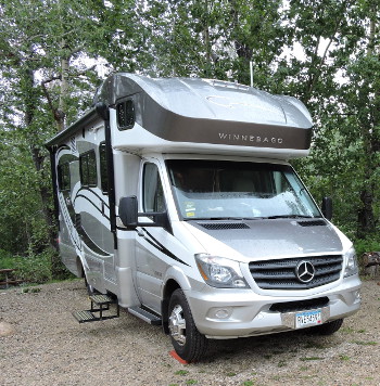
The first photo is of a Winnebago with the Norcold N3150. The fridge in this RV needed help in hot weather in addition to the protection of the ARP + Fan Control.
Following we will discuss the features of the Norcold refrigerator. Also shown is how to install the ARP boiler sensor and wiring.
Click here for post on Sprinter Forum "I installed a newer version 3.1 ARP on my 2016 Winnebago View24J."For further information on recommended fan install: ARP + Fan Control
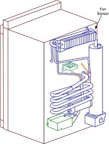
The N3104 is a 3.7 cubic foot fridge and the N3150 is a 5.3 cubic foot fridge. Both of these fridges are similar in the sense that they are controlled by electrical controls.
These fridges are prone to failure due to the fact that they are mostly in small RVs that can be used in day to day driving. As a result, these fridges are left running and parked off-level. The fridge will overheat and be damaged within 15 minuets when parked 3 degrees off level. For this reason, the ARP Control is a must for vehicles that are used often in a situation where damage may occur.
Please click here to see video of Norcold N3150 being protected by the Fridge Defend.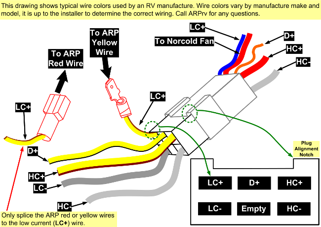
Download PDF printable drawing by clicking here.
This drawing shows the 6-connector plug that connects the Norcold fridge to the RV. In the lower right corner is the identification of the terminals within the plug. In order to wire the ARP Control, the lead marked LC+ (Low Current Positive) needs to be identified. The ARP will be spliced into this wire. The ARP red wire will connect to the battery side of the LC+ wire and the ARP yellow wire will connect into the end of the splice going to the Norcold fridge.
We recommend using a male and female insulated spade connector for the splice ends. This makes it easy to reconnect the splice if one wants to restore factory settings or troubleshoot the fridge.
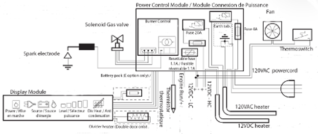
The wiring diagram to the left has been included to help if your wiring sticker has come off your fridge. The wiring image has been saved in a resolution that may be printed if needed.
Click here for further information and wiring diagrams.
Click here for Sprinter Forum photos of an N3150 control board we fixed.
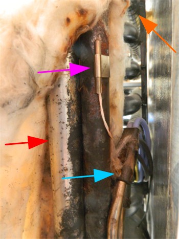
The ARP boiler temperature sensor is quite easy to install on the N31xx series. Some fridges may need to be removed for the install, some folks have chosen to just install the fan control until there fridge needs to be removed for service for the boiler sensor install.
This photo shows the proper location for the ARP sensor. Staring at the top orange arrow, the ARP sensor (purple arrow) shall be mounted below the top absorber coil (orange arrow). The ARP boiler sensor will be mounted on the boiler tube, the boiler tube is behind the flue tube (red arrow). The ARP sensor should be at least 1 inch above the electric heaters (blue arrow). Download the full installation instructions for further details.
If your fridge is not preforming properly on LP Gas, but works fine on shore power, the issue may be a plugged
filter in the refrigerators solenoid operated valve (SOV).
Click here for LP filter cleaning instructions.
Click here for LP filter cleaning video.
If your fridge is not preforming properly with 12V heater, but works fine on shore power, the issue may be an overheated trace on your control board. Click here for fix of common control board problem that results in 12V heater not working.
| # of LIGHTS | MEANING | POSSIBLE SOLUTION |
|---|---|---|
| 1 | Controller senses LP flame, but LP mode not selected. | Remove cover of gas burner check if flame present; gas valve stuck open; igniter wiring issues. See next error for more troubleshooting on this issue. |
| 2 | LP Igniter Issue |
Remove LP burner cover, check electrode gap,
clean burner, check wiring and ground for
LP igniter.
Click here for igniter adjustment. |
| 3 | Flame did not ignite. |
The flame attempts to ignite for 30 seconds.
Empty LP tank, high wind, low LP pressure, igniter adjustment,
can result in this error. Reset fridge by turning on/off,
if will not solve issue see this link:
Click here for filter cleaning and LP pressure adjustment. Manual shutoff valve is closed on LP solenoid. |
| 4 | 12V heater is set to turn on, but does not. | Click here for fix of common control board problem that results in 12V heater not working. |
| 5 | 12V heater is off, should be on. | Use link in above error code 3, test DC heater resistance using value in table below. Tap on relay seen in above link, may be stuck shut? Try cycling fridge on/off. |
| 6 | 12VDC voltage out of range. | Proper DC voltage range is between 10 to 15 volts checked at terminals LC+ & LC- seen in wiring drawing above. |
| 7 | Fridge set to Manual DC Mode and there is "no engine running" displayed. |
Check for 12VDC at HC+ and HC- leads seen in
drawing above.
Check the D+ signal wire for
proper signal.
Click here for fix of common control board problem that results in 12V heater not working. |
| 8 | 120VAC heating element failure. |
Check shore power, check both heating elements
for proper resistance using table below.
Click here to check heater resistance. Click here to check heater shore power and GFI safety |
| 9 | Shore power heater is on, should be off. | The control board relay is stuck closed. Try tapping on relay to free. Try cycling the fridge on/off a few times. |
| 10 | Shore power 120VAC out of range. | The proper shore power range is from 108 to 132VAC. |
| 11 | Fridge is in Auto Mode, but fridge cannot find an energy source. | Try cycling fridge on/off. Change out of the Auto Mode. Check LP, 12VDC, and 120VAC as described above. |
| 12 | Communications error. |
The display board on front of fridge is not
communicating (COM) with the back control
board:
Click here, the first photo shows the "COM", it is the brown arrow to the right, check this connection. |
| 13 | Thermistor failure, control is in backup operating mode. |
The control unit is not getting an input it needs to run.
Fridge thermistor has failed. Click here to check thermistor. Check all wiring connections, power down the fridge and then power up. |
| 18 | Fridge not able to start. | Preform all checks described above, this is a very ambiguous error we are aware. Start with the 12VDC supply to fridge to see if in range while attempting to start fridge. |
Please note that all of the following specifications are believed to be accurate. If any errors are found, please bring them to our attention as soon as possible. For critical specification please contact Norcold as they make changes to their specifications without notice.
| Item | Value | Units |
|---|---|---|
| ARP Control Boiler Temperature | See Note 1 Below | |
| N3104 Volume | 3.7 | cu. ft |
| N3150 | 5.3 | cu. ft |
| Off-Level Operating Limit | See Note 2 Below | |
| Temp Setting Range | 1 - 5 | 5 = Coldest | See Note 3 Below |
Fuses
| Item | Value | Units |
|---|---|---|
| Board 12V Fuse | 20 | Amp |
| 120VAC | See Note 4 Below | Amp |
DC Power
| Item | Value | Units |
|---|---|---|
| Automatic Ignition | 0.5 | Amp |
| Flapper Heater | 0.3 | Amp |
| DC Heater N3104 | 15.8 | Amp |
| DC Heater N3150 | 17.1 | Amp |
| Fan | 0.24 | Amp |
| Total Amp Draw N3150 | 18.14 | Amp |
AC Power
| Item | Value | Units |
|---|---|---|
| Operating Range | 108 - 132 | VAC |
| AC Heater N3104 | 1.8/66 | Amps/Ohms |
| AC Heater N3150 | 2.5/48 | |
| Measurement Conditions | 120 | VAC |
LP Gas
| Item | Value | Units |
|---|---|---|
| Gas Pressure | 10.5 - 11.5 | inch w.c. |
| Heat Input | not given | BTU/hour |
| Gas Jet | not given | |
| Gas Jet (new style) | not given | |
| Electrode to Burner Gap | 1/8" to 3/16" | inch |
NOTES
Note 1: 185-195°C - 365-383°F
Note 2: Dependent on ambient and ARP boiler temp.
Note 3: Thermistor Values
Note 4: 5 Amp type AGC fast acting.
If you cannot find what you need please use the Contact Us form on the top menu.