This page shows how to improve the efficiency and safety of your Norcold Polar N7V, N7X, N7LX, N8V, N8X, N8LX, N10LX, NA10LX RV fridge by install of the Fridge Defend by ARP
REQUIRED TO DOWNLOAD INSTALLATION INSTRUCTIONS - WEB PAGES ARE SUPPLEMENTAL - EACH VERSION OF CONTROL HAS INTRICACIES REQUIRING THE WRITTEN INSTRUCTIONS.
Instructions: Subjects are listed on left. Click the link to the right to go directly to the subject matter on this page.
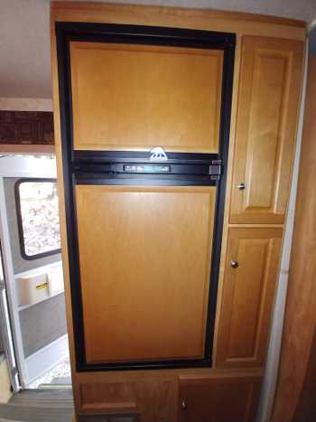
The N7V & N7X only differ by the control panel, they are both 6.5 cubic foot
refrigerators
The N7LX is the 3-way version of the N7X fridge.
The N8V & N8X only differ by the control panel, they are both 7.6 cubic foot
refrigerators
The N8LX is the 3-way version of the N8X fridge.
The first photo is of a Winnebago with the Norcold N7V. This fridge is a replacement for the stock N611 fridge that failed due to the fridge being operated off-level without the Fridge Defend protecting the cooling unit boiler. The Fridge Defend with the fan control was installed to help the fridge cool efficiently,
For further information on recommended fan install: ARP + Fan Control
For further information on Polar 7 see this post on iRV2: ARPrv Protection Device
We have tested this new series of fridge from Norcold, we are very impressed with their performance and would recommend them to any RV'er. They have increased refrigerated space while fitting into a smaller area, what else can an RV'er ask for? We also tested how easily the boiler overheats, they are like any other absorption type fridge, the fridge can fail due to boiler overheating. Please note that it is clear that Norcold determined that none of there recalls were effective for protecting the fridge from this type of failure, thus they do not have the typical boiler housing Thermal Switch nor a Thermal Fuse. The Fridge Defend is required on this fridge for efficiency, reliability, and safety.
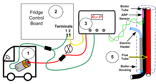
This is a basic overview of the wiring procedure for the two-way fridge. All one needs to do is splice in the Fridge Defend on the line supplying power to the fridge as seen in this image.
Please click here for further details.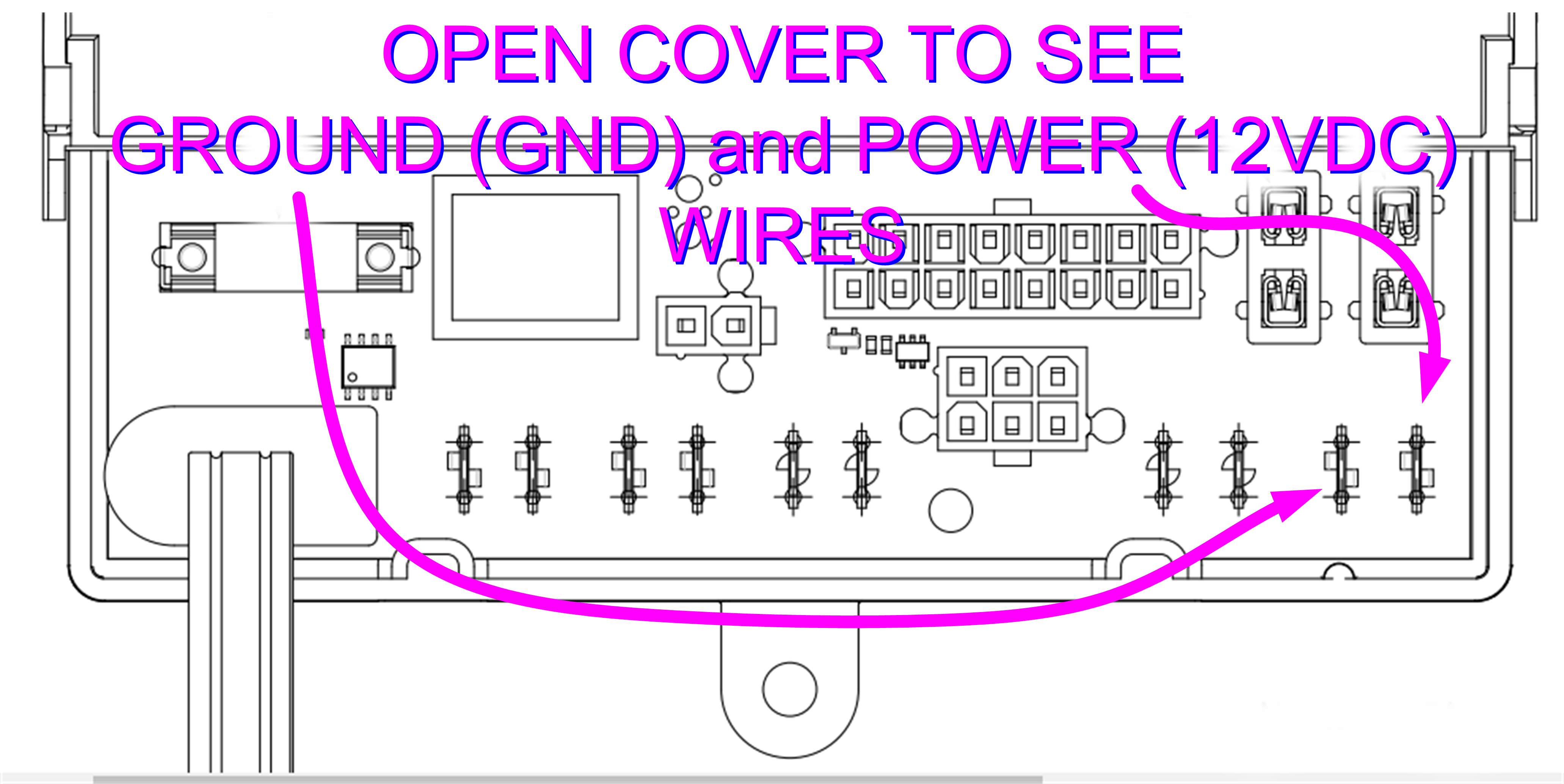
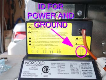
PLEASE TAP THUMBNAIL TO ENLARGE IMAGE
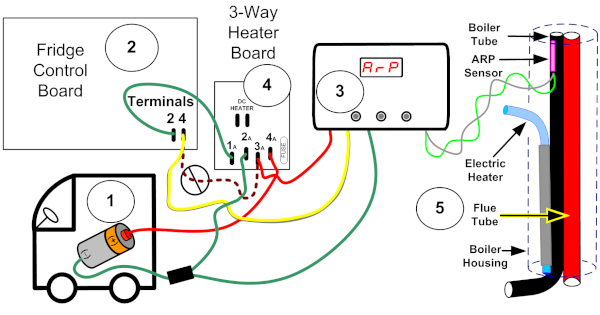
This is a basic overview of the wiring procedure for the 3-way fridge. All one needs to do is splice in the Fridge Defend between the 3-Way Board and the Fridge Control Board.
Please click here for further details.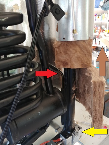
The ARP boiler temperature sensor is quite easy to install on the Norcold Polar series. In most cases the boiler sensor can be installed without removing the fridge as long as one can squeeze the bottom of the boiler housing to open it. As seen in this photo, the boiler housing was opened at the bottom and then slid up to gain access to the boiler tube. The YELLOW ARROW points to the burner assemble where one screw was removed. Move sheet metal boiler housing up a little, then the sheet metal boiler housing was squeezed to unlatch the bottom clip holding it together. Once the housing is opened on the bottom, slide the housing up (BROWN ARROW) above the electric heater (RED ARROW).
Some fridges may need to be removed for the install, some folks have chosen to just install the fan control until there fridge needs to be removed for service for the boiler sensor install.
Please view the remaining photos to get the big picture :)
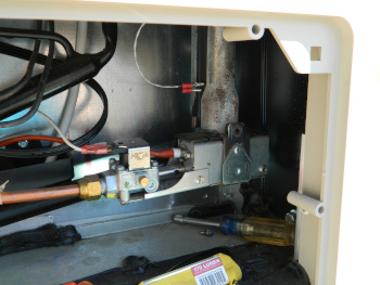
This photo shows the screw removed from the burner assembly (YELLOW ARROW ABOVE PHOTO) and the sheet metal boiler housing and insulation moved up to gain access to install the Fridge Defend boiler sensor without removing the fridge from the RV.
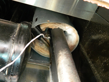
This photo is the same RV as the above photo, the camera is just looking up to where the boiler housing was slide above the electric heater. The Fridge Defend boiler sensor is clipped onto the boiler tube above the heater, see the next photo for more detail.
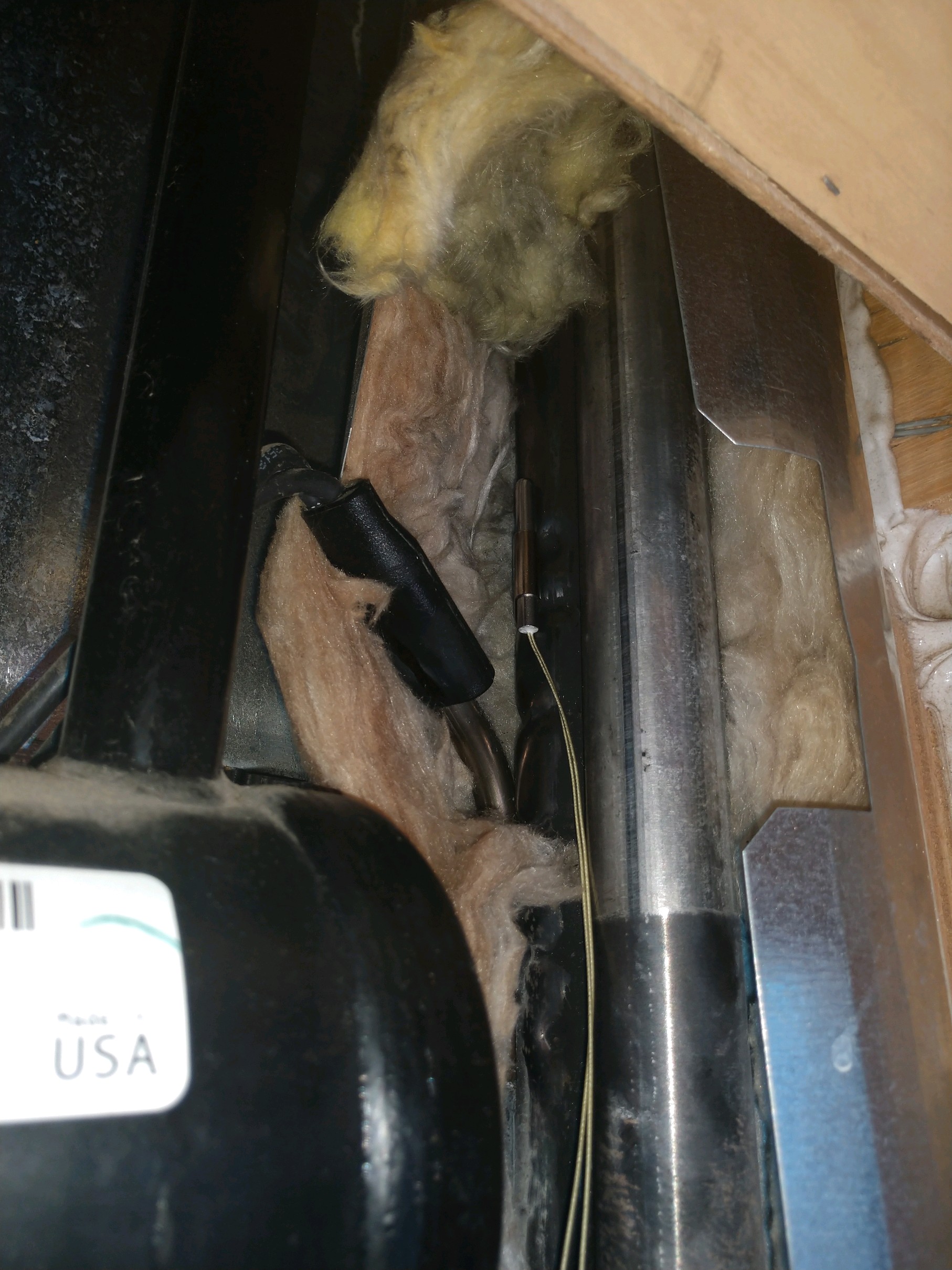
This photo shows the proper location for the Fridge Defend boiler sensor. This is a Norcold NA10LX in a slide-out application. Please follow the download instillation instructions for insulation of the sensor and wiring.
If your fridge is not preforming properly on LP Gas, but works fine on shore power, the issue may be a plugged
filter in the refrigerators solenoid operated valve (SOV).
Click here for LP filter cleaning instructions.
Click here for LP filter cleaning video.

| PIN NUMBER | MEANING | WIRE COLOR |
|---|---|---|
| 1 | Auxiliary Ground: Water Line heater, Fan, Cold Weather Heater | Black |
| 2 | Thermistor Ground: Refrigerated Compartment | White/Black |
| 3 | Interior Light Ground | Black/White |
| 4 | Thermistor: Refrigerated Compartment | Red/White |
| 5 | Interior Light 12VDC | Red |
| 6 | Auxiliary 12VDC: Water Line heater, Fan, Cold Weather Heater | Red |
| 7 | LP Gas Solenoid Valve 12VDC | White |
| 8 | N/C | No Wire |
| 9 | User Interface Ground | White/Violet |
| 10 | LP Gas Solenoid Valve Ground | White |
| 11 | Chassis Ground | Green/Yellow |
| 12 | User Interface 12VDC | Green (nice!) |
| 13 | Divider Heater | White |
| 14 | User Interface Communications (bi-directional) | Blue |
| 15 | N/C | No Wire |
| 16 | N/C | No Wire |

The N7V and N8V has an LED that indicates the error or fault. If there is any error shown on the LED, first try disconnecting all power to the fridge, wait for 2 minutes, then reconnect power to reset controller.
| LED | MEANING | POSSIBLE SOLUTION |
|---|---|---|
| Power On indicator is solid red | Fridge tried to start on selected energy source and failed | Try the manual mode if in auto.
Try the auto mode if in manual. Check for empty LP tank. Check shore power. Check Fridge Defend voltage to fridge function. See our troubleshooting guide. |
| Flash red on 1 time, off 5 seconds, repeat | AC Heater Fault |
Check shore power.
Check fuse in Norcold Control. Check heater resistance, should be 45.7 to 50.5 Ohms cold. 300W Heater. Click here for heater test. |
| Flash red on 2 time, off 5 seconds, repeat | Norcold Control Fault |
Check the LP gas solenoid valve wires.
Check LP gas solenoid valve coil resistance 74-92 Ohms. |
| Flash red on 3 time, off 5 seconds, repeat | Norcold Control Fault |
The stated error is "control board limit circuit is open".
Norcold requests that you replace the board, cry :/ |
| Flash red on 4 time, off 5 seconds, repeat | AC Heater Stuck On | If you are handy, the relay on the board can be replaced. In a pinch the control can be cycled on/off while tapping on the relay to try an un-stick the contacts. When the contacts stick, the relay is destroyed due to excessive heat or amperage. Check the heater ohms, see above 3rd row for values. Click here to check heater shore power and GFI safety |
| Flash red on 5 time, off 5 seconds, repeat | LP Gas Flame when flame should not be lit. |
Check the voltage to the LP gas solenoid, if there is voltage
when there should not, the relay is stuck on the control board,
see row above for suggestions.
The LP gas solenoid valve is stuck open, clean with solvent. Click here for filter cleaning and LP pressure adjustment. |
| Flash red on 8 time, off 5 seconds, repeat | 12VDC power supply low at fridge |
Use the Fridge Defend to check the voltage to the fridge.
Norcold does not give a specification for what "too low"
is. Most automotive controllers
will not function with less than 10.5VDC to the controller.
(ARP will operate down to 5VDC) |
| Flash red on 9 time, off 5 seconds, repeat | 120VAC power supply high at fridge |
Use the Fridge Defend to check the voltage to the fridge.
Norcold does not give a specification for what "too high"
is. Most automotive controllers
will not function with less than 16.5VDC to the controller.
(ARP will operate up to 20VDC) |
| Flash red on 10 time, off 5 seconds, repeat | The communications between the control panel and the main control board has stopped. |
All one can do is check the wiring,
otherwise there is a failure of one of the boards.
The blue wire in P1, terminal 14, and P1, terminal
3 of the operator interface are the
communications.
This wire should
have continuity
and not be
shorted to
ground.
Click here to check P1 & Main Board & Operator Interface P1 Connector. |
| Green LED, flash off 1 time every 20 seconds | The fridge is on AC and control is in the limp mode. |
Fridge thermistor has failed or the wiring is open.
Click here to check thermistor values. Click here to check thermistor. |
| Amber LED, flash off 1 time every 20 seconds | The fridge is on LP and control is in the limp mode. |
Fridge thermistor has failed or the wiring is open.
Click here to check thermistor values. Click here to check thermistor. |
| DISPLAY | MEANING | POSSIBLE SOLUTION |
|---|---|---|
| no FL & Audible Alarm | LP Burner did not ignite | Check LP, May be out of gas?
Light burner on stove, if will not light pressure issue. Change out LP bottle, turn off fridge and try again. Check the manual shut-off valve on LP solenoid valve. Click here for filter cleaning and LP pressure adjustment. Click here for video for filter cleaning and LP pressure adjustment. |
| no AC & Audible Alarm | AC Heater Power Fault |
Check shore power, no AC
available to the fridge.
Check fuse in Norcold Control. Check RV circuit breaker. |
| AC HE & Audible Alarm | AC Heater Fault |
Start by checking the above code 'no AC' suggestions.
Check AC heater resistance, should be 45.7 to 50.5 Ohms cold. Amp draw 2.38-2.63A AC Click here for heater test. Click here to check heater shore power and GFI safety |
| dc HE & Audible Alarm | DC Heater Fault |
Start by checking the above code 'no AC' suggestions.
Check DC heater resistance, should be 6.7 to 7.8 Ohms cold. Amp draw 16-18A DC Click here for heater test. Click here to check heater shore power and GFI safety |
| dc Er & Audible Alarm | Loss of communications between main and DC control board. | Check main board terminals P4 and DC boards P1 |
| Lo dC & Audible Alarm | 12VDC power supply low at fridge |
Use the Fridge Defend to check the voltage to the fridge.
Norcold does not give a specification for what "too low"
is. Most automotive controllers
will not function with less than 10.5VDC to the controller.
(ARP will operate down to 5VDC) |
| HI dc & Audible Alarm | 12VDC power supply high at fridge |
Use the Fridge Defend to check the voltage to the fridge.
Norcold does not give a specification for what "too high"
is. Most automotive controllers
will not function with less than 16.5VDC to the controller.
(ARP will operate up to 20VDC) |
| no dt & Audible Alarm | The communications between the control panel and the main control board has stopped. |
All one can do is check the wiring,
otherwise there is a failure of one of the boards.
The blue wire in P1, terminal 14, and P1, terminal
3 of the operator interface are the
communications.
This wire should
have continuity
and not be
shorted to
ground.
Click here to check P1 & Main Board & Operator Interface P1 Connector. |
| Temperature setting LED flashes 1 second on & 1 second off | The fridge thermistor temperature sensor has problem. |
Fridge thermistor has failed or the wiring is open..
Click here to check P1 terminals 2 (gnd) & 4 (signal). Click here to check thermistor values. Click here to check thermistor procedures. |
| Sr & Audible Alarm | Fault with control board. |
Check LP gas solinoid valve wire connections at main
control and valve.
Click here to check P1 terminals 7 (12VDC) & 10 (gnd). Disconnect the main power to the control board, wait 30 seconds, re-power up to see if error is gone? If one has the Fridge Defend, just do the post install test with the SetUp button to turn off power to fridge. Click here to check all main board P1 terminals for proper signals, power & grounds. |
The following value are approximate, there is error in test leads and other factors. Be sure to check all connections, the connections in the fridge can rust. We do not recomend using an ice bath, the water can get into the thermistor.
| TEMPERATURE (°F) | RESISTANCE (kΩ) |
|---|---|
| 85 | 8.1 - 9.0 |
| 80 | 9.1 - 10.0 |
| 75 | 10.1 - 11.0 |
| 70 | 11.1 - 12.0 |
| 60 | 12.1 - 13.0 |
| 50 | 15.5 - 16.5 |
| 40 | 22.5 - 23.5 |
| 35 | 24.5 - 25.5 |
| 33 | 28.5 - 29.5 |
| 32 | 30.0 - 32.0 |
If you cannot find what you need please use the Contact Us form on the top menu.