The Fridge Defend is needed on the Dometic models RM1272, NDA1292, NDR1292, NDA1492, & NDR1492. These RV refrigerators are no longer made and they are a unique size, thus hard to replace.
REQUIRED TO DOWNLOAD INSTALLATION INSTRUCTIONS - WEB PAGES ARE SUPPLEMENTAL - EACH VERSION OF CONTROL HAS INTRICACIES REQUIRING THE WRITTEN INSTRUCTIONS.
Instructions: Subjects are listed on left. Click the link to the right to go directly to the subject matter on this page.
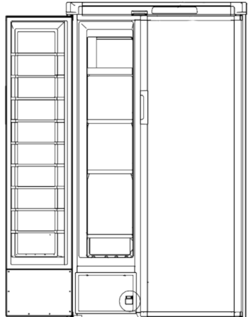
The Dometic 1292 & 1492 series of fridge is found in Fifth Wheels and Class-A motorhomes. These fridges are no longer made, thus is is highly advisable to install the Fridge Defend by ARP on these RV referigerators to insure a long life.
Please click here to see how the ARP Control protects your fridge.
Due to the heat that these referigerators generate, we strongly advise using the ARP + Fan Control to increase the efficiency and reliability of these units.
Click here to see how the ARP + Fan Control saves you money.
This section shows the temperature sensor install on the models NDR1292, & NDR1492. The procedures illustrated here applys to all of the left Dometic left hand boiler fridges.
Please see Dometic Left Hand Boiler Temperature Sensor Install Video
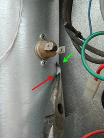
The first step is to disengage the tab at the back side of the heater door access.
The green arrow shows where a screwdriver was used to bend up the corners of the tab. The red arrow shows the use of needle nose pliers bending the tab so that the bottom of the NDR 1492 boiler housing can be opened.
Sometimes this tab is toward the back of the fridge, therefore not easily accessible. There are two methods to deal with this, one is to skip directly to the next step without disengaging this tab. In this case, aluminum HVAC tape can be used to reseal the access door, see images below.
The second method is to grab the boiler housing with both hands and twist the housing around to gain access to the tab.
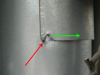
To disengage the bottom of the door, cut a short slot - as shown by the red arrow. This slot allows the door to be disengaged from the cooling unit boiler housing by sliding the door to the right as shown with the green arrow. Please note that the door is disengaged in this photo.
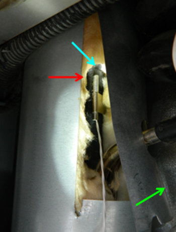
This photo shows a Dometic NDA1292, the heater access door has been opened, the green arrow points in the direction to move the access door out of your way. The ARPrv temperature sensor has been clipped on the cooling unit boiler tube.
Please note that the sensor is above the electric heaters. The blue arrow points at the crimp in the Dometic cooling unit boiler tube. The ARPrv temperature sensor tip (red arrow) shall be in contact with the Dometic boiler tube. Restated, the temperature sensor tip shall not be straddling the air space created by the Dometic NDR 1492 boiler crimp.
The manufacturer puts the crimp in the tube to hold the percolator tube within the boiler tube. Please see our How an Absorption Refrigerator Works to understand the basic principles of an Absorption Refrigerator.
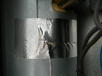
This photo is of a Dometic NDR1292 after insulating the ARPrv temperature sensor and including extra insulation within the boiler housing, reverse the above order to shut the heater access door. Tape the bottom of the heater access door, as seen in this photo with HVAC Tape.
Click here to view the RM7030 page to see more ARP sensor install information.
Click here if your fridge has a boiler thermal switch that is wired in line with the power supply.
Please click here for the ARP blower fan and temperature sensor installation.
Please see the full ARP User Manual and Installation Guide for more information needed before using your ARPrv Control.
Please note that all of the following specifications are believed to be accurate. If any errors are found, please bring them to our attention as soon as possible. For critical specification please contact Dometic as they make changes to their specifications without notice.
| Parameter | Value |
|---|---|
| Fridge Defend Boiler Temperature | 185-195 degC |
| Fan Control Absorber Coil Temperature | 120-135 degF |
| Off-Level Operating Limit | Click Here |
| Minimum DC Power Supply | 8.5 VDC |
| Maximum DC Power Supply | 18 VDC |
| Maximum AC on 12VDC Supply Line | 6 VAC |
| Board 12VDC Fuse | 3 A |
| Board AC Fuse | 5 A |
| VAC Operating Range | 100-132 VAC |
| DC Heater Power Rating | --- |
| DC Heater Current | --- |
| DC Heater Resistance per Heater (cold) | --- |
| DC Fuse | 30 A |
| AC Heater Power Rating (Both Heaters) | 420 W |
| Current | 3.5 A |
| Heater Resistance per Heater (cold) | 34.3 Ohm |
| Gas Pressure | 10.5-11.5 Inch-H2O |
| Gas Jet | #76 |
| Gas Thermocouple | 25-35 mVDC |
| Electrode to Burner Gap | 3/16 inch |
| Thermistor @ 33degF to 35degF | 7k-10k Ohm |
| Parameter | Value |
|---|---|
| Fridge Defend Boiler Temperature | 185-195 degC |
| Fan Control Absorber Coil Temperature | 120-135 degF |
| Off-Level Operating Limit | Click Here |
| Minimum DC Power Supply | 9.6 VDC |
| Maximum DC Power Supply | 22 VDC |
| Maximum AC on 12VDC Supply Line | 6 VAC |
| Board 12VDC Fuse | 3 A |
| Board AC Fuse | 5 A |
| VAC Operating Range | 100-132 VAC |
| DC Heater Power Rating | 215 W |
| DC Current | 18 A |
| DC Heater Resistance per Heater (cold) | 0.67 Ohm |
| DC Fuse | 30 A |
| AC Heater Power Rating | 420 W |
| Current | 3.5 A |
| Heater Resistance per Heater (cold) | 34.3 Ohm |
| Gas Pressure | 10.5-11.5 Inch-H2O |
| Gas Jet | #76 |
| Gas Thermocouple | 25-35 mVDC |
| Electrode to Burner Gap | 3/16 inch |
| Thermistor @ 33degF to 35degF | 7k-10k Ohm |