The Fridge Defend by ARP helps keep your Dometic reliable while increasing safety and efficiency. This is the install page for the 3, 4, 5, 6 & 8 cubic foot series of manual control Dometic fridge.
REQUIRED TO DOWNLOAD INSTALLATION INSTRUCTIONS - WEB PAGES ARE SUPPLEMENTAL - EACH VERSION OF CONTROL HAS INTRICACIES REQUIRING THE WRITTEN INSTRUCTIONS.
Instructions: Subjects are listed on left. Click the link to the right to go directly to the subject matter on this page.
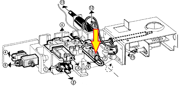
The Dometic 3, 4, 5, 6 & 8 cuft fridges are very efficient as long as the cooling unit boiler is not allowed to overheat. The problem with these refrigerators is that they are mostly found in slide-in campers, class-b, and other everyday driver type RV conversions. As a result there is a high failure rate due to off-level use and other factors associated with everyday driving that destroys the cooling unit. These refrigerators have the controls the bottom of the fridge. A thermocouple interrupter and relay are required to control manual control RV refrigerators, these parts are not provided with the standard Fridge Defend kits.
Please click here to see how the ARP Control can make your Dometic safer, more reliable & efficient.

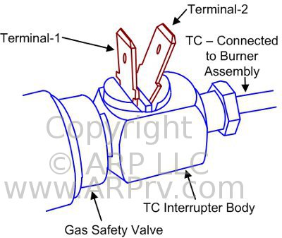
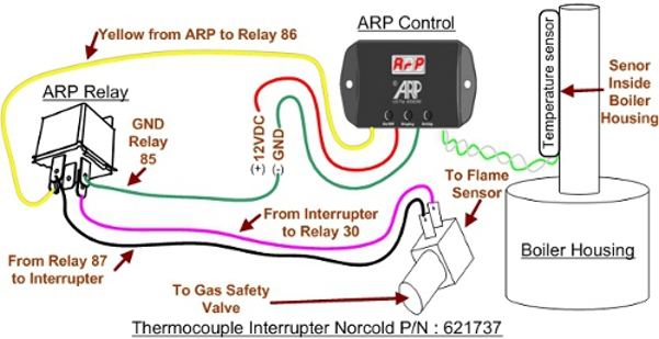
This next drawing shows the thermocouple interrupt adaptor attached to the gas safety valve and the thermocouple (TC). The TC interrupt has two electrical leads identified as terminals 1 & 2. As seen in the next image, these two terminals will be wired to the relay terminals 30 & 87.

This image combined with the two above shows the compleate install and wiring of the Fridge Defend. Starting on the right, the relay interrupts the thermocouple signal to the gas safety valve, thereby turning off the gas flame it there is a cooling unit overheat situation. Below are links to further details for wiring.
Click here for interrupt adapter wiring details.
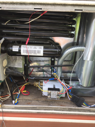
This photo shows a relay that turns off the power to the shore power by wiring to the
Fridge Defend and to the 120VAC heater. Click the link below for the relay used:
Shore Power Relay
Please note that all of the following specifications are believed to be accurate. If any errors are found, please bring them to our attention as soon as possible. For critical specification please contact Dometic as they make changes to their specifications without notice.
| FRIDGE MODEL: | RM2310 | RM2410 | RM2510 | RM2610 | RM2810 | Units |
|---|---|---|---|---|---|---|
| ARP Control Boiler Temperature | 170-180 | 170-180 | 170-180 | 170-180 | 180-190 | Celsius |
| Off-Level Operating Limit | dependent on ambient and ARP boiler temp. | |||||
| Minimum DC Power Supply | 9.6 | 9.6 | 9.6 | 9.6 | 9.6 | VDC |
| Maximum DC Power Supply | 22 | 22 | 22 | 22 | 22 | VDC |
| Maximum AC on 12VDC Supply Line | 6 | 6 | 6 | 6 | 6 | VAC |
| FRIDGE MODEL: | RM2310 | RM2410 | RM2510 | RM2610 | RM2810 | Units |
|---|---|---|---|---|---|---|
| Board AC Fuse | 5 | 5 | 5 | 5 | 5 | Amp |
| Board 12VDC Fuse | 3 | 5 | 3 | 5 | 3 | Amp |
| FRIDGE MODEL: | RM2310 | RM2410 | RM2510 | RM2610 | RM2810 | Units |
|---|---|---|---|---|---|---|
| Operating Range | 100-132 | 100-132 | 100-132 | 100-132 | 100-132 | VAC |
| FRIDGE MODEL: | RM2310 | RM2410 | RM2510 | RM2610 | RM2810 | Units |
|---|---|---|---|---|---|---|
| DC Heater Power Rating | 125 | 125 | 175 | 215 | 215 | Watts |
| Current | 10.4 | 10.4 | 14.6 | 17.9 | 17.9 | Amps |
| Heater Resistance per Heater (cold) | 1.15 | 1.15 | 0.82 | 0.82 | 0.82 | Ohms |
| Fuse | 30 | 30 | 30 | 30 | 30 | Amps |
| FRIDGE MODEL: | RM2310 | RM2410 | RM2510 | RM2610 | RM2810 | Units |
|---|---|---|---|---|---|---|
| AC Heater Power Rating | 160 | 160 | 185 | 295 | 325 | Watts |
| Current | 1.3 | 1.3 | 1.5 | 2.5 | 2.7 | Amps |
| Heater Resistance per Heater (cold) | 92 | 92 | 75 | 48 | 44 | Ohms |
If you cannot find what you need please use the Contact Us form from the top menu.