In order to keep your Dometic 8 series fridge reliable, safe, and efficient the installation of the Fridge Defend is required. This series of RV fridge requires the Fridge Defend + Fan Control to remain cool in hot weather.
I’ve been on the road for a week since I installed the Fridge Defend on my Dometic RML8555, the performance of the fridge is
significantly improved. We have driven across the hot and humid south from San Antonio to Atlanta and
we are holding 3 degrees in the freezer and 33 degrees in the fridge. I am a big fan of the inside and outside fans ...
they are making a difference and do not kill my battery like the
other noisy fan I had.
Thanks for the improved efficiency and safety! M Schwarz
REQUIRED TO DOWNLOAD INSTALLATION INSTRUCTIONS - WEB PAGES ARE SUPPLEMENTAL - EACH VERSION OF CONTROL HAS INTRICACIES REQUIRING THE WRITTEN INSTRUCTIONS.
Instructions: Subjects are listed on left. Click the link to the right to go directly to the subject matter on this page.
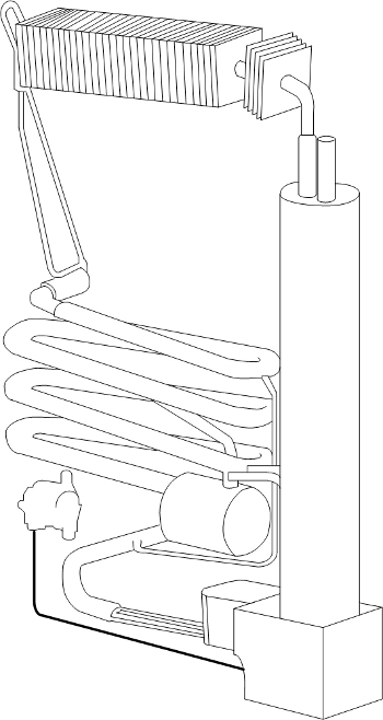
The Dometic 8 Series of refrigerator are used in Class-B and Class-C type RVs. For example, the RML8555 is found in Winnebago VIA Class-C. Due to the side-vent arrangement on these types of RV the Fridge Defend + Fan Control is a must to keep these RV refrigerators working in hot weather.
The figure to the left is a cooling unit for a Dometic RMw 8xyz, where the lower case letters are defined for the models in the following manner:
w: This value can take on the following letters; S= housing with step; T= TecTower; D= large; O= single door fridge with oven.
8: Dometic 8 series RV fridge.
x: 4= 486mm width; 5= 535mm width.
y: 0= standard depth; 5= 55mm depth; 6= 65mm depth.
z: 0= Manual Control; 1= Automatic Control (MES = manual energy select); 5= Automatic Control (AES = automatic energy select).
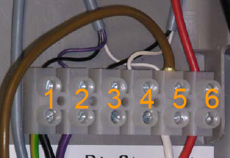
This image shows the terminal block, the terminals are identified as follows:
(1) Negative/Ground 12 Volt connector for electronics (black wire).
(2) Positive 12 Volt connector for electronics (violet wire).
(3) D+ alternator signal - optional (black wire).
(4) S+ solar panel signal - optional (white wire).
(5) -12VDC heater (white wire).
(6) +12VDC heater - 16A fused (red wire).
Please click here for detailed wiring instructions.
Please click here for the ARP blower fan and temperature sensor installation.
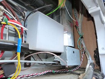
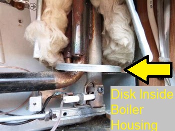
This photo is of an RMD 8501 burner and boiler assembly. The boiler housing needs to be opened to install the ARP Control boiler sensor. The boiler housing can be squeezed to unlatch the joint that holds the sheet metal together.
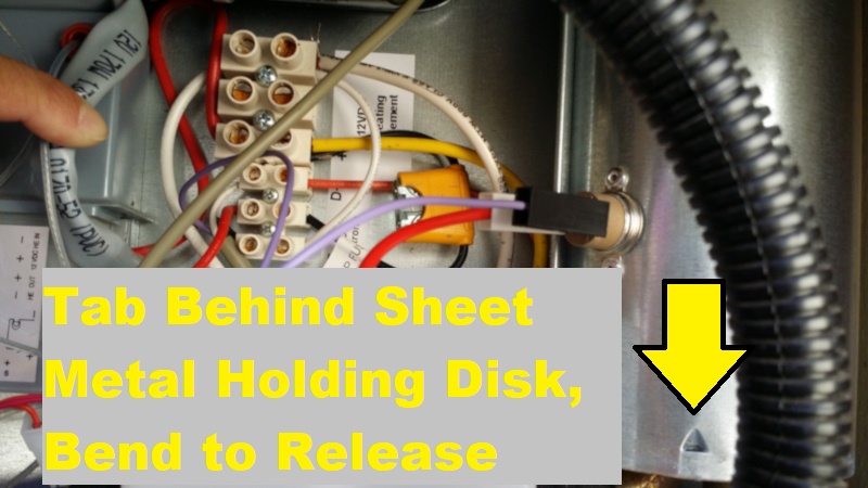
The yellow arrow in this image shows the location where a tab holds a disk at the bottom of the boiler housing. This tab needs to be bent down to release the disk that is holding the bottom of the boiler housing closed. After all 3 tabs are bent down, remove the inner disk, and then the boiler housing can be squeezed to open, as seen in the below photo.
This photo shows the burner assembly and the boiler housing opened for the installation of the ARP temperature probe. Please note that the burner assembly is at the bottom of the flue tube. The burner attaches to the flue tube with one Phillips screw. To the left of the flue tube is the boiler tube, the boiler tube is easy to identify because the electric heaters are welded to the boiler tube. It is on the boiler tube that the ARP sensor is mounted.
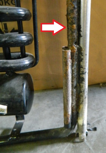
This is a photo of an RLM 8555 cooling unit without the burner assembly or the boiler housing and insulation blocking the view of the respective tubes within the boiler housing.
The arrow points to the approximate location where the ARP sensor should be installed. Be sure to insulate the sensor and wire exiting the boiler housing very well, the insulation around the wires will protect the wires from being cut by the sheet metal.
Please click here to see further information regarding the location of the ARP boiler sensor.
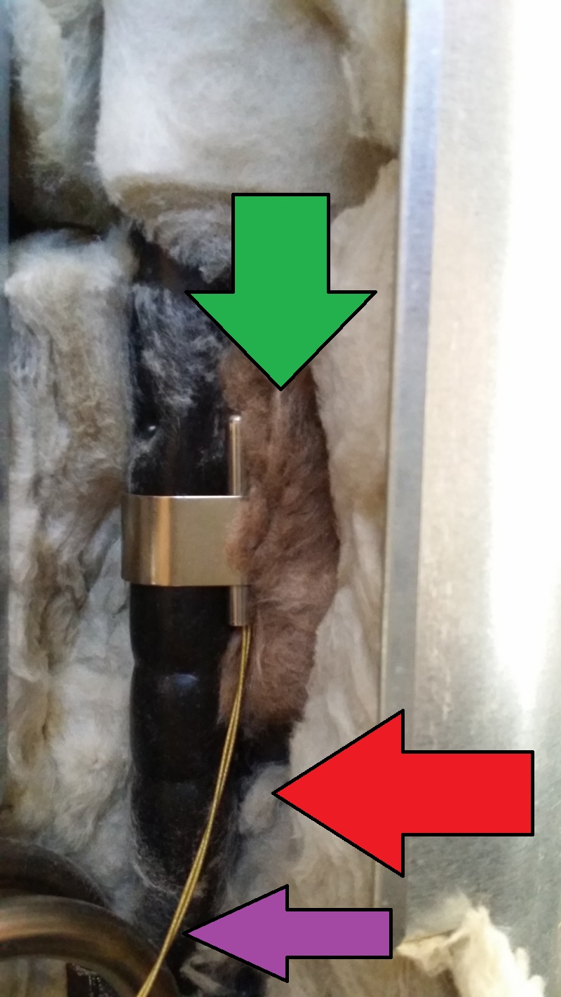
This photo shows the Fridge Defend safety sensor clipped onto the boiler tube. Please note the fiberglass insulation, GREEN ARROW, packed between the flue tube and the sensor.
Also note that the sensor can be mounted closer to the heaters (RED ARROW). If sensor is close to the heaters, just insulate the sensor very well.
Do wrap fiberglass insulation around the Fridge Defend sensor wires (PURPLE ARROW). If these wires are not protected, the sheet metal can cut the wires.
Please click here to see further information regarding the location of the ARP boiler sensor.
Please note that some refrigerators need to be scooted forward, or removed to install the boiler sensor. The installer needs to check for instillation clearances before opening the Fridge Defend package.
Please note that all of the following specifications are believed to be accurate. If any errors are found, please bring them to our attention as soon as possible. For critical specification please contact Dometic as they make changes to their specifications without notice.
| Parameter | Value |
|---|---|
| Fridge Defend Boiler Temperature | 185-195 degC |
| Fan Control Absorber Coil Temperature | 120-135 degF |
| Off-Level Operating Limit | Click Here |
| Minimum DC Power Supply | 10.5 VDC |
| Maximum DC Power Supply | 22 VDC |
| Maximum AC on 12VDC Supply Line | 6 VAC |
| Board 12VDC Fuse | 1 A |
| Board AC Fuse | --- |
| VAC Operating Range | 103-132 VAC |
| DC Heater Power Rating | 130 W |
| DC Current | 10.8 A |
| DC Heater Resistance per Heater (cold) | 0.85 Ohm |
| DC Fuse | 16 A |
| AC Heater Power Rating | 135 W |
| Current | 2.5 A |
| Heater Resistance per Heater (cold) | 106.7 Ohm |
| Gas Pressure | 10.5-11.5 Inch-H2O |
| Gas Jet | --- |
| Gas Thermocouple | 25-35 mVDC |
| Electrode to Burner Gap | --- |
| Thermistor @ 32degF | 27.7 kOhm |
| Parameter | Value |
|---|---|
| Fridge Defend Boiler Temperature | 185-195 degC |
| Fan Control Absorber Coil Temperature | 120-135 degF |
| Off-Level Operating Limit | Click Here |
| Minimum DC Power Supply | 10.5 VDC |
| Maximum DC Power Supply | 22 VDC |
| Maximum AC on 12VDC Supply Line | 6 VAC |
| Board 12VDC Fuse | 1 A |
| Board AC Fuse | --- |
| VAC Operating Range | 103-132 VAC |
| DC Heater Power Rating | 170 W |
| DC Current | 14.2 A |
| DC Heater Resistance per Heater (cold) | 106.7 Ohm |
| DC Fuse | 30 A |
| AC Heater Power Rating | 190 W |
| Current | 1.6 A |
| Heater Resistance per Heater (cold) | 75.8 Ohm |
| Gas Pressure | 10.5-11.5 Inch-H2O |
| Gas Jet | --- |
| Gas Thermocouple | 25-35 mVDC |
| Electrode to Burner Gap | --- |
| Thermistor @ 32degF | 27.7 kOhm |
Refrigerators with an electronics system, either MES or AES, indicates a malfunction by the LED (Triangle Icon with !) or display flashing.
If a failure occurs, the indicator LED (Triangle Icon with !) flashes simultaneously. In the case of AES models an acoustic alarm sounds.
| MES Type Fridge | AES Type Fridge | FAILURE | |
|---|---|---|---|
| LED is flashing | 230 is flashing | 230V mode: "120VAC" not available or voltage too low | |
| LED is flashing | 12 is flashing | 12V mode: "12V" not available or voltage too low | |
| LED is flashing | GAS is flashing | GAS/Auto mode: Flame not ignited | |
| All temperature setting LEDs are flashing | All temperature setting LEDs are flashing | Temperature sensor defective, refrigerator works on mid temperature setting | |
| LED + all temperature setting LEDs are flashing | HE1 is flashing | 120VAC - Heating element defective | |
| LED + all temperature setting LEDs are flashing | HE2 is flashing | 12V - Heating element defective |